On Monday I put out a CQ SSTV on 20m and when the transmission was finished I looked over to the receive screen and saw the waterfall display was empty. No signal was being received. Not even noise.
I went out to the shack and sure enough the FT757 was lifeless. No lights, no noise, nothing.
I have been working in the radio maintenance game for most of my life and when I don’t see lights where I should, I instinctively look at the power source, in this case, the VK Powermaster.
My VK Powermaster has no voltage meters or output indicators on it, just an illuminated mains power switch. This switch was dark so I knew there was no mains power to the unit. A quick check of the other 240 V appliances in the same power point showed the mains was still present. I unplugged the VK Powermaster from the wall and checked the fuse. One 3 Amp fuse – blown.
I replaced the fuse and the second one blew straight away. Hmmm. This is looking serious.
I built the VK Powermaster over 25 years ago and it has powered many rigs along the journey and has given me faultless service until now. The only modification I have made is a reset switch that releases the over current protection circuit in the event of shut down. I did this because the original design required the mains power be turned off long enough for the filter capacitors to discharge. From memory this took about 2 minutes. I got sick of waiting after each shut down so I fitted a momentary switch that removes the wait. I can’t recall exactly how this works but once I find a circuit diagram I will post details.
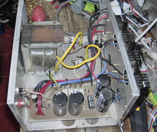
So with fuses blowing at switch on I took the cover off and started working through the circuit from the mains input toward the regulator circuit. The VK Powermaster is a linear regulator typical of the 1980s era having an 18 Volt AC transformer, a four way diode bridge rectifier, four big electrolytic capacitors, and four 2N3055 pass transistors as the major parts of the circuit.
A visual inspection showed the wiring in and out of the mains switch and the transformer was good so I disconnected the bridge rectifier from the transformer, replaced the fuse and switched on again. This time the fuse survived. This told me the fault was between the bridge rectifier and the DC output.
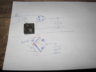
Since the rectifier has Faston terminals it was easy to remove it from circuit and test it out. With the diode tester on my Fluke DMM I measured between the terminals and found two diodes were good and two diodes were short circuit. The two shorted diodes were effectively placing a short across the output of the transformer. Hence the large current flow and the fuse failure.
A trip to Jaycar yesterday saw a new 400V 35A bridge rectifier fitted and the VK Powermaster lives again.
73


4 Responses to VK Powermaster fails after more than 25 years