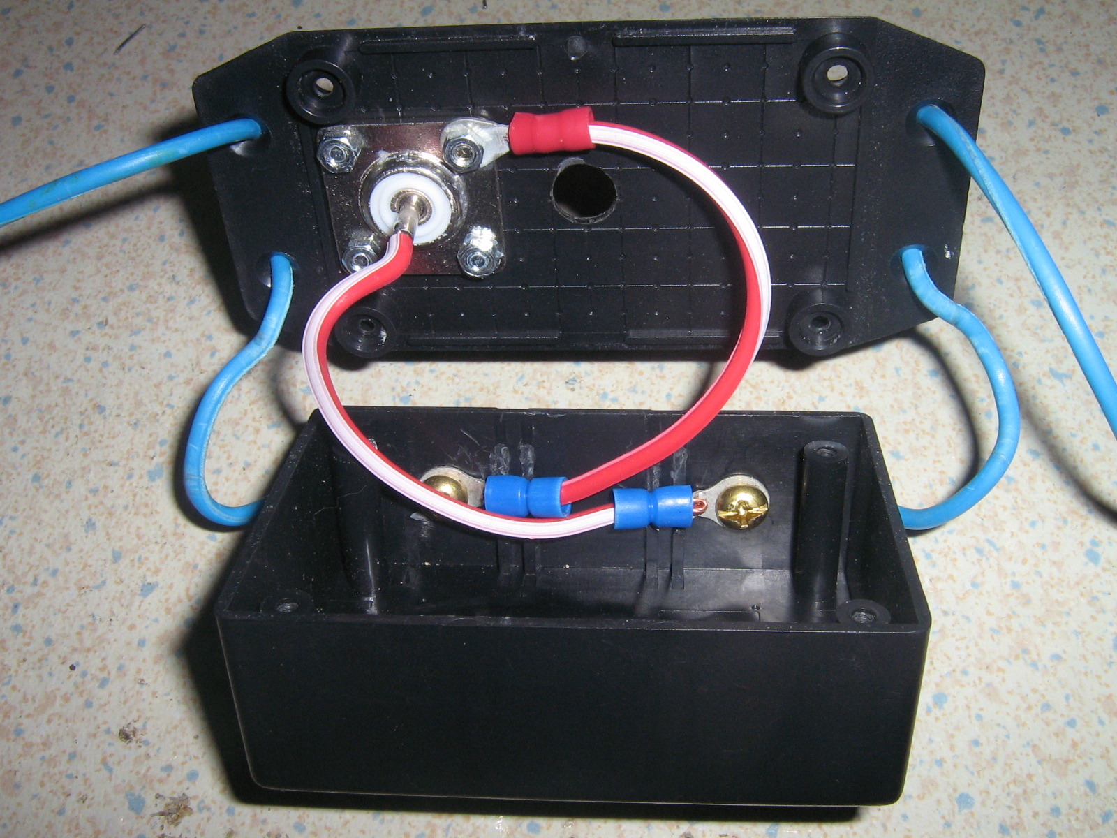
Termination box
Wanting to work more than one or two bands with a portable antenna I decided to build a lightweight inverted vee antenna that could be supported by a 10 metre long fiberglass squid pole. The antenna is designed to cover 10, 15, 20, 40 and 80 m bands. I have centred the tuning around 28.490, 21.200, 14.200, 7.100 and 3.600 MHz. The 10 m squid pole is a standard design pole, rated as ‘medium duty’ from Haverford in Sydney. Phil, VK3JNI, was kind enough to source a large quantity of these and sold them off to SRESU members in early 2010. This antenna is my number one antenna for SOTA activations.
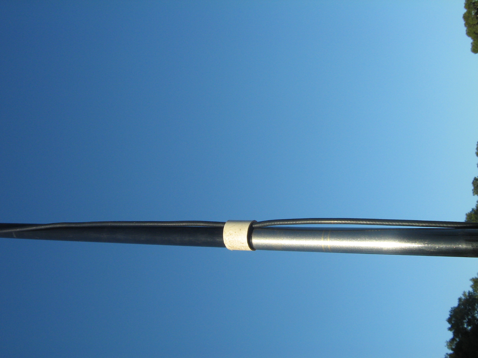
Strain relief
At first I tried hanging the antenna from the top of the squid pole however I found the top section to be too flexible and it caused the pole to bend over too much. To overcome this I bought a small box from Jaycar. It is a UB5 flange mounted Jiffy box, catalog number HB6016. The box measures 83 x 54 x 31 mm. The flange, or bulkhead, mounting is useful to provide strain relief by passing each leg of the antenna through the mounting holes. I drilled a 9 mm hole through the box and pass the squid pole through the holes. The box sits about 1.1 m down from the tip of the pole at the beginning of the second section. Inside the box is a simple termination without a balun. I have used brass screws to connect the wire elements of the inverted vee. I also place a piece of pipe, 25 mm diameter, over the pole and the coax to help take the weight of the coax off the upper sections of the squid pole. This strain relief is positioned about 3.4 m down the pole.
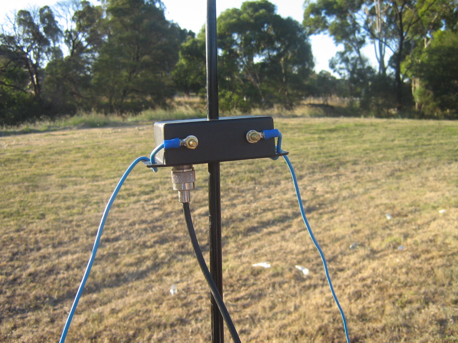
Termination box
The ends of the antenna each have 2.7 m of rope on them and these can be pegged to the ground or tied off to trees. The higher bands are not affected by the ends of the antenna being close to the ground but the SWR on the 80 m band can change quite a bit if the ends are raised up. The wires in the inverted vee are cut to the lengths shown in the diagram below. With these lengths I get an SWR of less than 1.2:1 on the 10, 15, 20 and 40 m bands.
On 80 m the SWR varies quite a bit depending on how high the ends of the antenna are above the ground and the nature of the soil under the antenna. I have included a 1 m length of wire at the end of each leg to allow for the antenna to be quickly shortened or lengthened if needed. The legs can also be folded back on themselves to improve the SWR on 80 m.
Band selection method
I have used RCA line plugs and sockets to break and make the antenna at various points to enable different bands to be worked. I have soldered the antenna wire to both the centre and outer conductor of the RCA plug and socket.
Changing bands is a simple matter of lowering the squid pole and plugging or unplugging the relevant connection for the band in use. Each connection has a plastic plate behind it acting as a strain relief. I have labeled each plate to assist choosing the correct band. If I want to work 10 m I need to open both 10 m sockets. If I want to work 40m I need to close the 10, 15 and 20 m sockets and open both of the 40 m sockets. The connections are arranged in increasing value working down from the apex of the antenna. So the first connection down is 10 m, then 15 m then 20m followed by 40 m and then 80 m. If I wanted to add additional bands I could by cutting the wires at the correct point and inserting another connection.

Strapped to bollard
The base of the squid pole is either strapped to a bollard or similar or held in place with four guy ropes. When I use ratchet straps to hold the pole I also use a piece of PVC pipe to protect the pole from being crushed.
Early on I found that the squid pole would often collapse when it was installed perfectly vertical. To overcome this I pull the top of the antenna to one side by about 150 mm to get a slight bend in the pole. This increases the friction on the telescopic joins and discourages collapse. It is worth spending a little extra time to get the ends of the antenna directly in line with the pole as any misalignment will cause the pole to lean over.
This antenna is intended to be a portable antenna and would normally only be set up for a few hours. I don’t know how the RCA connectors will perform in the long term if they get wet but they are cheap enough that I could replace them if they become a problem. When not in use I roll the antenna up on to two plastic rope holders that I bought from the local Bunnings warehouse. This helps keep the antenna tidy and makes it quicker to deploy in the field.
Wrapped ready for transport
The antenna takes about 15 minutes to set up as it can get a bit fiddly finding the right places to tie the ends off. I can pack it away in about 8 minutes. The antenna itself, not including the squid pole, weighs about 2 kg.
This squid pole antenna was my main antenna on the VK3SAT 2012 activation of French Island and it performed very well.
Similar antennas, known as linked dipoles, can be found at the CQHQ blog, G6WRW page, Ham Antenna Blog and 2M0IOB’s bog. WA0KAQ details a heavy duty jumpered dipole on his portable ham shack page.
 |
| Pre-tune wire measurements 10/15/20/40/80 m antenna – click to enlarge |
In June 2013, for the SOTA 12 metre challenge, I made a second antenna for three bands only. This antenna works on 12, 20 and 40 metre bands and is lighter to carry and quicker
to set up than the 5 band version. It has 10 metres of rope at each end to ensure the vee is
well spread out. The pre-tune measurements for this antenna are given below.
 |
| Pre-tune wire measurements 12/20/40 m antenna – click to enlarge |
 |
| Switched inverted vee antenna in use during the 2012 VK3SAT French Island activation |
1 July 2017 update
After 4 years and more than 100 activations, my 3 band linked dipole required some maintenance. The RCA plug/socket for the 20m band had failed and both plug and socket had broken.
Today I replaced them with red Anderson PowerPole connectors. I’m hoping to get many more activations from this antenna.

Pingback: Returning to Mt Ritchie, VK3/VC-003 | VK3ZPF Ham Radio Blog
Pingback: Snowy River National Park, VKFF-0455 | VK3ZPF Ham Radio Blog
Pingback: Errinundra National Park, VKFF-0158 | VK3ZPF Ham Radio Blog
Pingback: Activation of French Island Marine National Park, VKFF-0950 | VK3ZPF Ham Radio Blog
Pingback: French Island National Park activation, VKFF-0622 | VK3ZPF Ham Radio Blog
Pingback: Mt Saint Phillack, VK3/VT-006 activation | VK3ZPF Ham Radio Blog
Pingback: SOTA on a bike – good or bad idea? | VK3ZPF Ham Radio Blog
Pingback: Terrick Terrick National Park activation | VK3ZPF Ham Radio Blog
Pingback: The Paps VK3/VE-204 activation | VK3ZPF Ham Radio Blog
Pingback: Mitchell River National Park activation | VK3ZPF Ham Radio Blog
Pingback: Strange link dipole shenanigans? - VK3BQ
Pingback: Armstrong 500 activity | VK3ZPF Ham Radio Blog
Pingback: Three summits and two National Parks in one weekend | VK3ZPF Ham Radio Blog
Pingback: My portable antenna/s | vk5pas
Pingback: Recent radio activations | VK3ZPF Ham Radio Blog
Pingback: Four old summits in one day | VK3ZPF Ham Radio Blog
Pingback: Multiband Linked Dipole using Switches | VK3YY
Pingback: Keith Roget Award Activation Weekend 2013 | VK3ZPF Ham Radio Blog
Pingback: Mystical Unicorn DX Wire Ultra Light.. | VK3BQ
Pingback: A lightweight Link Dipole | vk3pf