I got a pleasing note from Steve G6ALU after update # 2 saying it looked like I was doing fine and that I should take my time. I have slowed a little but not because I am troubled by construction, or on Steve’s advice, but because my son, VK3FASH, had his birthday a couple of days ago.
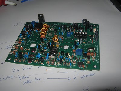
Since my last update I have completed bags 3 & 4. Bag 3 had 51 X 100 nF capacitors along with many inductors and transformers to be wound. Mounting the capacitors was easy enough although I did have one left over. I can’t see any empty holes so it must be a bonus.
Transformers T4, T5 and T6 use 38 SWG enamelled copper wire inside a small binocular core. For those not familiar with SWG sizes, 38 SWG is 0.152 mm (0.002 “) in diameter.
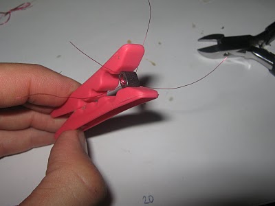
Winding wire so thin needs a fair amount of concentration and steady hands. I found it a great help to hold the binocular core in a clothes peg while winding and tinning the leads.
I was quite pleased with the results of all my transformers and inductors with the exception of T2. T2 uses 22 SWG wire (0.711 mm) which I found difficult to fit all the windings into the core and the last two turns look very untidy. I doubt it will affect the performance and the board would look messier if I now try and remove the transformer just to rewind it.
Steve suggests in the manual to secure the small transformers to the board with silicon after testing but I have used double sided tape to hold them in place.
Bag 3 also contains the electrolytic capacitors and these, being polarised components, must be fitted the correct way around. I have always wondered why the capacitors are marked showing the negative lead, rather than the positive lead? Nearly all circuit diagrams and marked boards highlight the positive terminal. Just one of those strange things I guess.
As I had done with the ceramic capacitors, I sorted the electrolytic capacitors into foam to make selection easier.
Bag 4 has the transistors, voltage regulators (that look like transistors), trim pots and crystals in it. I sorted the transistors and regulators into groups, but not into foam, to make the job easier. Looking at the part numbers on the BC547 has proved to me that my eyesight is not what it used to be and maybe it is time for some glasses.
Bag 4 had no real challenges, except getting the right part in the right place. The PCB screen layout sure makes this task easy. Q5, ZTX651, is a strange looking device in as much as the front and back of the device are parallel and the only difference is a small chamfer on each side. Particular care was required with this part.
I took the fuse from bag 5 and fitted it to the fuse holders to assist in soldering it in. Without the fuse I found the holders too hard to keep in place.
While I was in bag 5, I unwrapped the LCD and found that it has no backlight. Since a lot of my portable activity is at night, and that is when 80m really comes alive, I will look to substituting a different display with a backlight. I saw some displays in the specials bin at Altronics before Christmas so I will pop in there today and see if they are suitable.
73


2 Responses to MKARS80 Update # 3