40 & 80 m Portable Trapped Dipole
Sometimes the need to operate on two bands from a single antenna is required. Although a combined antenna is a compromise over two seperate dipoles, sometimes the available space or supports prohibit such.
One compromise antenna I use is a trapped dipole.
A trapped dipole relies on parallel tuned traps to ‘disconnect’ the additional wire when used on the specified band. The antenna described here is for operation on 40 m and 80 m.
At the resonant frequency the two traps shows a high impedance, in series with the antenna wires, and very little RF energy goes past the trap. As a result the antenna ‘looks’ electrically shorter than it really is. At frequencies other than the resonant frequency the traps pass nearly all the RF energy past the trap to the rest of the antenna.
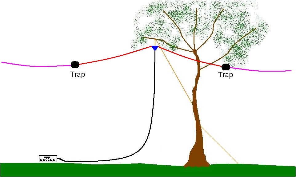
Looking at the sketch above, when working 40 m only the red wires are part of the antenna but when using 80 m the red and purple wires are the antenna.
Making the 40 m traps
The traps consist of 15 turns of insulated wire wound on a 42 mm OD PVC pipe 60 mm long. The wire I used is plastic coated, 2.25mm external diameter. The inner conductor is 24 strands of 0.2 mm diameter copper. The wire is terminated at each end with a crimp eye lug.
Inside the coil is a length of RG58 coaxial cable about 800mm long, open at one end and terminated to eye lugs at the other end.
At each end of the PVC pipe I have drilled a hole and a bolt, inserted from the inside, joins the coax lug to the coil lug, with the coax on the inside and the coil on the outside. As this is a portable antenna I have included wing nuts to allow the antenna wires to be easily attached and removed.

Once assembled wrap the coil with PVC electrical tape to hold the coil in position before proceding to tune the trap.
Once assembled the open ended coax is trimmed until the trap is resonant at the frequency of desired operation. Some texts suggest tuning either higher or lower than the desired frequency of operation, but I have had good results with traps tuned on the frequency of interest.
Tuning the 40 m traps
Tuning can be done with either a GDO or a signal generator and RF meter. I use the latter method.
Using the set up above, tune the RF generator until the RF meter dips sharply. This is where the trap is resonant. This should be below the desired frequency before trimming is commenced.
Trim a smal amount off the open end of the coax.
Retune the RF generator to the sharp dip again.
Repeat this process until the trap is resonate near your desired frequency.
Before reaching the desired frequency tuck the coax inside the pipe, leaving about 50mm sticking out one end.
Continue tuning until the desired frequency is achieved.
Fine tuning can be achieved by trimming only the braid, as shown above, rather than both the braid and the inner.
Once tuned cover the open end of the coax with PVC tape and tuck into the pipe.
Repeat with the second trap.
Tuning the antenna
Once the traps are tuned the antenna is constructed and installed into position for final tuning. The 4 antenna wires should start about 11m long before tuning.
During the tuning process it is OK to strip and wrap the wire around the bolt until the final trimmed length is achieved. Once the final length is found terminate the antenna wire in an eye lug at each end.
I found the best results by first trimming the 40m wires until the SWR was about 1.8:1 on 40 m then tuning the 80 m wires until the SWR on 80 m was about 1.6 :1.
With each band close to tuned I alternated trimming between 40 m and 80 m until an SWR of 1.3:1 or better is achieved on each band.

When tuning trim about 20 mm off the wire each time. There is interaction between each wire and you will notice the 80 m SWR is affected each time the 40 m wires are trimmed and a lesser change to the 40 m SWR when the 80 m wire is trimmed.
Once the tuning is complete the antenna wires should be terminated in eye lugs for ease of future set up.
Adding 20 m traps
Two 20 m traps can be added to include a third band if desired. For 20 m traps use 9 turns of wire on a 42 mm PVC pipe and 500 mm of RG58 coax to begin with.
The antenna wire lengths before trimming are 5.5 m between balun and 20m trap, 5.5 m between 20 m trap and 40 m trap and 11 m between the 40 m trap and the end of the antenna.
The tuning process is the same as for the 40/80 dipole, excpet the 20 m wires are trimmed first to an SWR of 1.8:1, followed by the 40 m wires then the 80 m wires. Repeat until the SWR on each band is below 1.3:1.

 Once assembled wrap the coil with PVC electrical tape to hold the coil in position before proceding to tune the trap.

 When tuning trim about 20 mm off the wire each time. There is interaction between each wire and you will notice the 80 m SWR is affected each time the 40 m wires are trimmed and a lesser change to the 40 m SWR when the 80 m wire is trimmed.
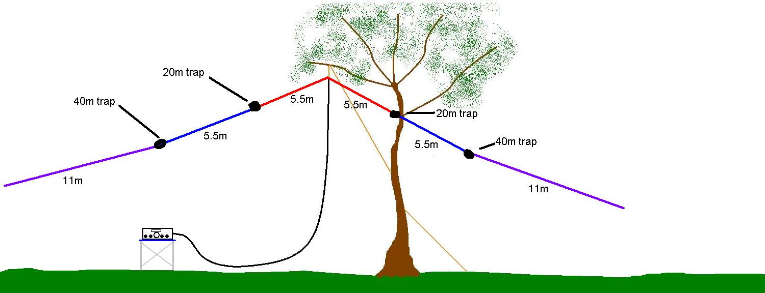
Pingback: VK shires contest 2010 | VK3ZPF Ham Radio Blog