This is a new section to my blog where I will detail what is currently on the work bench. It may be a kit under construction, a radio under repair or some dust from inactivity. Whatever it is, if it’s on the bench and worthy of publishing, this is the title under which it will be found.
I found a need for a 100 Watt dummy load when I wanted to test the power output of the FT757 GX after learning it had damage in the 24 – 29 MHz low pass filter section.
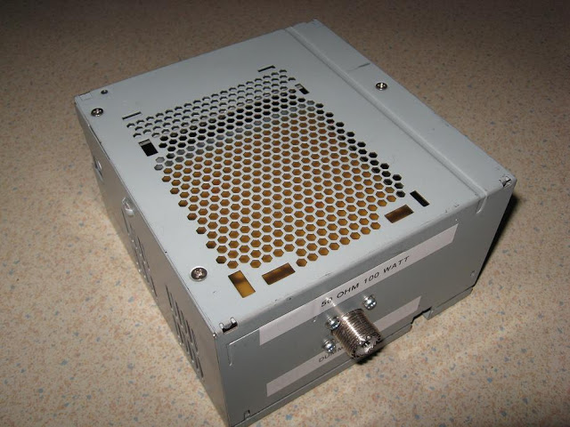
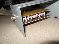
The dummy load is made of 111 5600 Ohm 1 Watt carbon resistors connected in parallel, between two sheets of blank PCB material. This is then housed inside a disused computer power supply that has retained the 12 Volt DC fan.
The resistors came from Futurlec who have been very good with parts supply for my other projects. I order on line and about two weeks later they arrive. At the same time I also ordered an Amp meter for my VK PowerMaster but that will the topic of another Watts on the bench.
The first step in construction was to cut all the resistor leads to the same length. To do this I used a small piece of PVC pipe with a slot through it. I just placed the resistor in the slot and then cut the lead. Each resistor lead was then the same length.
Next was to bend them all the same. Again I used a length of PVC pipe with a slot and bent the resistors to suit.
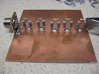
After preparing the resistors I soldered the SO 239 connector to the lower board then started by soldering the middle row of resistors to the same board. The resistors were joined together as pairs before soldering them to the board. I put the two boards together and soldered one resistor in each corner to keep the boards in place while I solder the middle row to the top board.
Progressively I worked from the inside out, following the layout plan, adding resistor pairs as I went along. After finishing a row of resistors I would measure the resistance of the load and compare this to the calculated value given how many resistors I had fitted at the time. Remembering of course that I had four extra resistors in circuit, one in each corner. After 74 resistors were soldered in place I removed the four corner resistors as they were no longer needed to hold the boards apart.
The original layout plan allowed for 118 resistor to be fitted. This meant that if all my resistors, being +/- 5 % tolerance, were 5 % high I could still achieve 50 ohms. As it turned out I needed only 111 resistors so some of the corner resistors were not needed.
Once all soldering was done I drilled some holes in the lid of the box and screwed the connector into place. This was a bit tricky and next time I might solder brass nuts to the connector to ease this task a little.
All that needs to be done now is to add an RF choke to the DC lead for the fan and put a power socket on the fan and it’s done.
All up it took about 10 hours to complete and cost $5.04 for the resistors, $5.00 for postage and $2.00 for the SO239 socket.
73


