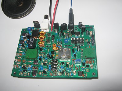
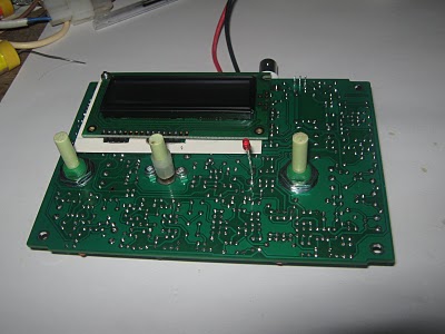
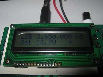
Well, it’s all getting a lot closer to working.
After my last update I went off to Altronics to look in the specials bin at some back lit LCD. Unfortunately the displays on offer were not back lit. I have continued on with the supplied display and I will order one with a back light next time I am getting parts from Futurlec.
My next bag of bits was bag 5, Bag 5 has such goodies as the potentiometers, Polyvaricon capacitor and the sockets.
I fitted all these without any trouble. I’m going to use a SO239 socket when I finish but for now I have fitted the BNC socket. It should be the only component that I have to de-solder and I hope I can do this easily thanks to the over sized pads and holes that it mounts in.
I have also added two power leads to the board where the internal battery connects. I’m not planning to use an internal battery, or the proved coaxial DC socket, but have a short fly lead with a mini T plug. This is the same arrangement I have on all my other radios so, along with the SO239 socket, the MKARS80 will not require any special leads or coax.
Having fitted these last few parts it left only the PIC chip and the LCD to be fitted. In the manual Steve recommends powering up and checking the +5 and +8 Volt supplies before inserting the PIC chip and display. This is good advice and I followed it accordingly.
Power on – no smoke and some noise from the speaker. This is a good start. The +5 and +8 Volt power supplies are OK. Time to add an antenna and have a listen around.
A quick tune through the band found a signal sounding like RTTY coming in quite strong. I was very pleased that at least the receiver was working.
Power off and add the PIC chip and display.
There is no challenge to the PIC, just place it carefully in the socket, checking of course that the socket, and chip are the right way around. It would have been a shame to get this far and blow up the only component I can’t just go down the road and buy.
The LCD confused me as I couldn’t quite make out the instruction about mounting the top left corner. I read through it a number of times and looked at the PCB as well. I didn’t look at the LCD. Once I started looking at the LCD and the PCB and where the connections needed to be made, it all made sense.
After arranging the screw and pushing in the first three wires from the left I found it very difficult to get the fourth wire in. I didn’t have the holes and the connector underneath aligned exactly. I loosened the screw and moved the LCD so I could get the most right wire in. Having done this the remaining wires were easy to insert. I soldered the wires to the LCD and then removed the LCD before trimming the wires. I just wanted to be sure all the wires were the same length into the socket and that I hadn’t missed one. All was good so I trimmed the wires to suit.
In the manual Steve also suggests placing a cardboard or plastic insulator between the LCD and the main PCB to prevent any unintended connections. Five minutes of handiwork with a pair of scissors and a Stanley knife and such an insulator was made. I wrote my call sign and the date on the cardboard so that later I, or others, will know when I built the radio.
I reassembled the LCD and prepared for switch on. The LCD fired up all black, as expected, and a quick adjustment of R29 saw the characters appear. So far so good.
I did the frequency alignment as described using C38 and got full coverage of the 80m band. Using a frequency counter I adjusted C83 for as close to 10.000 MHz as I could get. I’m not confident it is 100% correct but I can adjust it later after on air tests or using my DDS reference oscillator. For now 9.99970 MHZ is close enough.
I set the band pass capacitors C54, C68 and C79 to look just like the picture in the manual. I’m sure the pass band is fairly wide and these settings are not critical. Again I can always come back to them later.
I connected a power meter and dummy load to the BNC output and using a mono 3.5mm plug in the microphone socket got the radio in to transmit mode. I later read further down the manual and saw a warning about transmitting for longer than a few seconds without a heatsink on the IFR510 MOSFET (Q1).
Having the radio now in transmit, and with an ammeter in line with the power, I noted the initial transmit current as 0.26 Amps. I carefully adjusted R2 to increase the bias in the final amplifier until the overall current rose to 0.31 Amps. As mentioned in the warning about long transmissions, the bias current rose as Q1 got warmer.
I then tuned my FT757 GX, with a 30 cm length of wire for an antenna, on to the same frequency as the MKARS80 output and adjusted R59 and C103 for minimum S meter indication. At first I had S7 showing and I was able to reduce this to S1. I then draped the 30 cm length of wire I was using as an antenna on the FT757 GX over Q1 and the S meter came back to S7. Further adjustment got the carrier level down to S2. I have an RF probe somewhere that I built when testing my BITX 20 so I can check this again later.
At this point I was happy everything was working as it should and, since it was now almost midnight and I had to be up at 6:00 am I finished for the night.
73


