Today was the day I made a big mistake. I’m sure I will work a way around it but for 30 seconds of care it could have saved hours of extra work.
Today I decided to keep pressing ahead with the kit as I was now so close to being able to get the radio on air.
After learning that Q1 really needs a heatsink for extended transmit I set about putting my MKARS80 into the supplied box.
I downloaded the front panel drilling template from the website and printed it out, making sure to select no scaling in my printer set up.
I measured the template and it was exactly the required size.
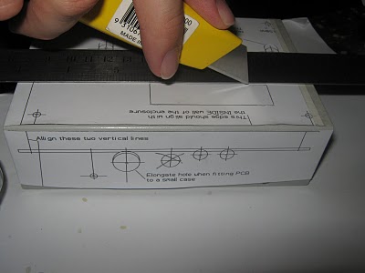
With some care I lined the template up on the front panel and taped it into place with masking tape. I then, with significantly less care, stuck the side template on the box. I then drilled all the holes. First with a 1 mm pilot drill and then a 3 mm drill.
I then marked with a Stanley knife the areas where the holes needed to be elongated and also the LCD cut out. I was so pleased with how it was going I even took a picture showing how I was using the knife and a steel ruler to mark where the LCD cut out was. If you look carefully at this photo you can see where I made my mistake.
The template says to line up two parallel lines on the side template with the mounting holes on the front. I’m not sure if my eyes were playing tricks or I was just careless but, as the photo clearly shows, the lines are out by about 3.5 mm.
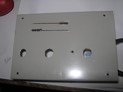
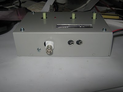
As a result of this error the holes on the side panel were out by about 3.5 mm. This meant that once I had drilled all the holes and elongated them as required the board wouldn’t fit. The only answer for this was to enlarge the holes some more, and then some more after that. The hole for the Q1 heatsink didn’t need to be enlarged as I just tilted the FET over until it was in the right position.
The final result looks really bad and it detracts from all the good work I had done on the inside assembly.
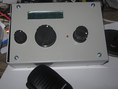
You can see in another photo how I cut out the LCD hole. I drilled 4 holes along each long edge then cut along with a metal saw. A few more holes along the short sides and the bulk of the metal was gone. I tidied the opening up with a flat file and, unlike the side panel, it come up looking good.
After I got the board to fit I finished the assembly and tried the radio out on air. I measured the output power at 4 Watts PEP and the current drain is 1.13 Amps. The output seems low as I was expecting at least 6 Watts. I will need to look into this further.
I gave a few CQ calls on a couple of frequencies but I got no response. It was about 2 pm and 80 m is normally very quiet at that time of the day.
Later in the evening I gave the radio another try and heard three radio nets in progress and all were good signals coming in to me.
I found a quiet frequency and called CQ a few times and, low and behold, VK3ZZ, Ross, answered my call. His opening comment to me was, “I hope you can hear me alright, I am running home brew at about 10 Watts.” I said the copy was fine and that I too was running home brew but only 2 Watts. I don’t know what happened to the 4 Watts I had earlier but now it was peaking at only 2 Watts. We had a long chat about his radio and mine and then he went inside to put the kids to bed and I came inside to escape the heat.
Tomorrow I will look more into the low output power and try a few different microphones. I will also put a tone generator into the microphone input and see what output that gives me.
If I can’t get any success with that I may need to rewind T2 as this was the transformer I was not happy with when I made it and it is in the output transmitter chain.
If I can’t get satisfaction on my own I can always send an email to the MKARS80 Yahoo support group.
73


